A compact small-scale jet engine engineered to demonstrate high-speed propulsion principles with precision, efficiency, and real-world aerospace applicability.
This project focuses on the development of a small-scale jet engine as the foundation for a future go-kart propulsion system. Designed entirely in CAD with an emphasis on manufacturability, the engine incorporates processes such as laser cutting, milling, and turning to ensure practical production. Early validation was carried out through 3D-printed prototypes, allowing the design to be tested and refined before full-scale fabrication. Serving as both a demonstration of precision engineering and a stepping stone toward larger applications, this project represents a key stage in advancing compact propulsion technology.
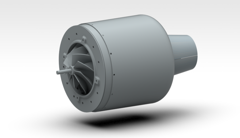
Fig 1. Cut-out Side view
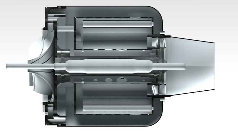
Fig 2. Rendered, Cut out side view
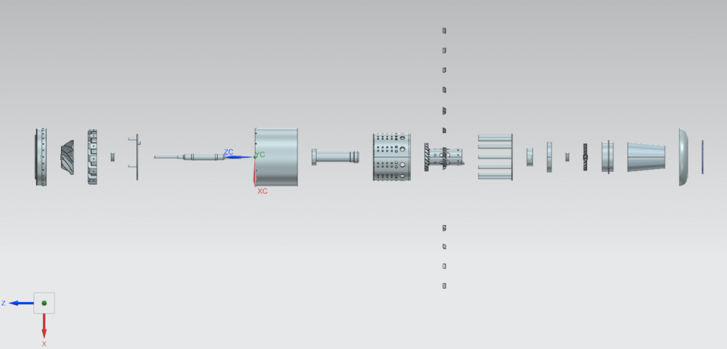
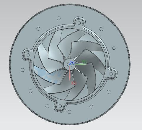
Fig 3. Exploded assembly
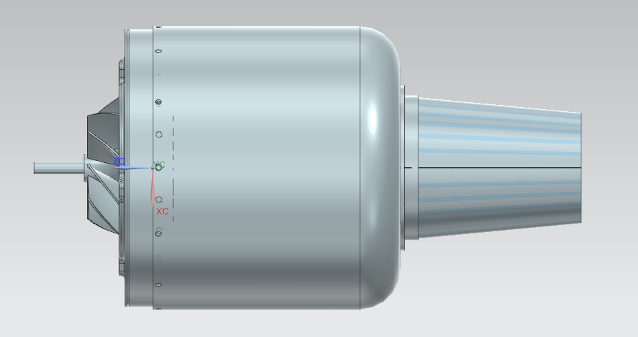
Fig 4. Side view
Fig 5. Front View CAD Assembly
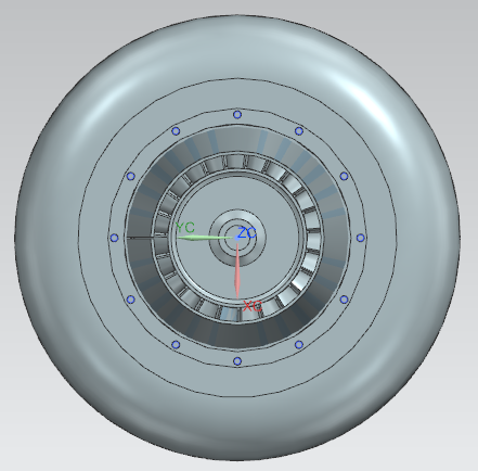
Fig 6. Back View CAD Assembly
Design and Development The CAD models above illustrate the complete design process of the small-scale jet engine, from detailed cutaway sections to exploded assemblies. Each component was modeled with manufacturability in mind, ensuring compatibility with processes such as laser cutting, milling, and turning. The exploded view highlights the modular architecture of the engine, which simplifies both fabrication and assembly. Front and rear perspectives further demonstrate the aerodynamic shaping of the compressor and turbine stages, key to achieving stable thrust.
This design stage establishes the foundation for prototype validation through plastic 3D printing before transitioning into full-scale metal fabrication. By carefully balancing precision, functionality, and manufacturing feasibility, the project bridges the gap between conceptual aerospace design and practical implementation.
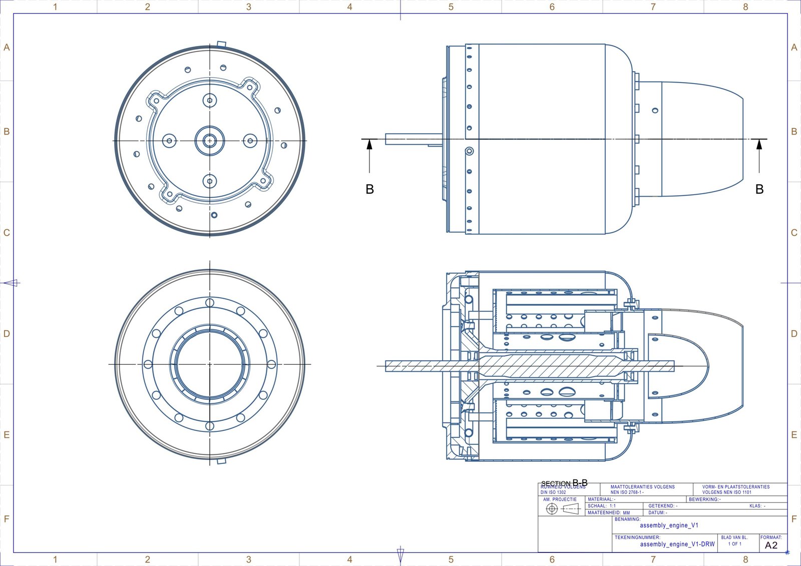
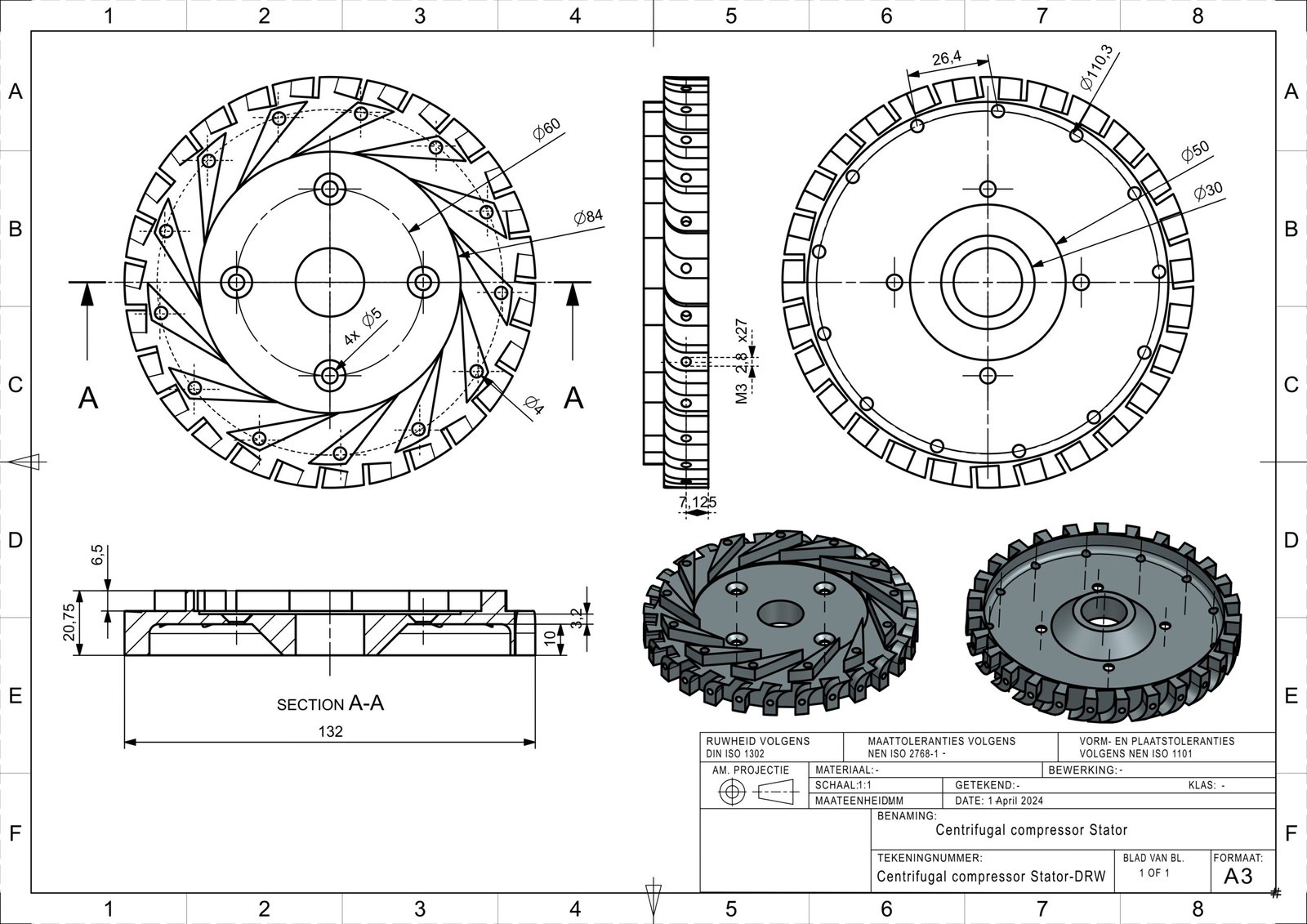
Technical Drawings To translate the CAD model into a manufacturable design, a complete set of technical drawings was produced. These drawings specify dimensions, tolerances, and material considerations, ensuring each component can be fabricated with accuracy using milling, turning, and laser cutting processes.
The sequence begins with the full assembly of the jet engine, followed by detailed drawings of the key subsystems and parts: the compressor stator, combustion chamber, axle, axle cover, outer casing, and compressor stator cap. Together, these documents provide the foundation for precision manufacturing and serve as the link between digital design and physical realization. Only some Technical Drawings from the components are shown below.
Full Assembly – Complete technical drawing showing overall system integration and the relationship between all major engine components.
Compressor Stator – Guides and stabilizes airflow in this single-stage design, ensuring smooth delivery into the combustion chamber. Manufacturable using step file on the milling machine
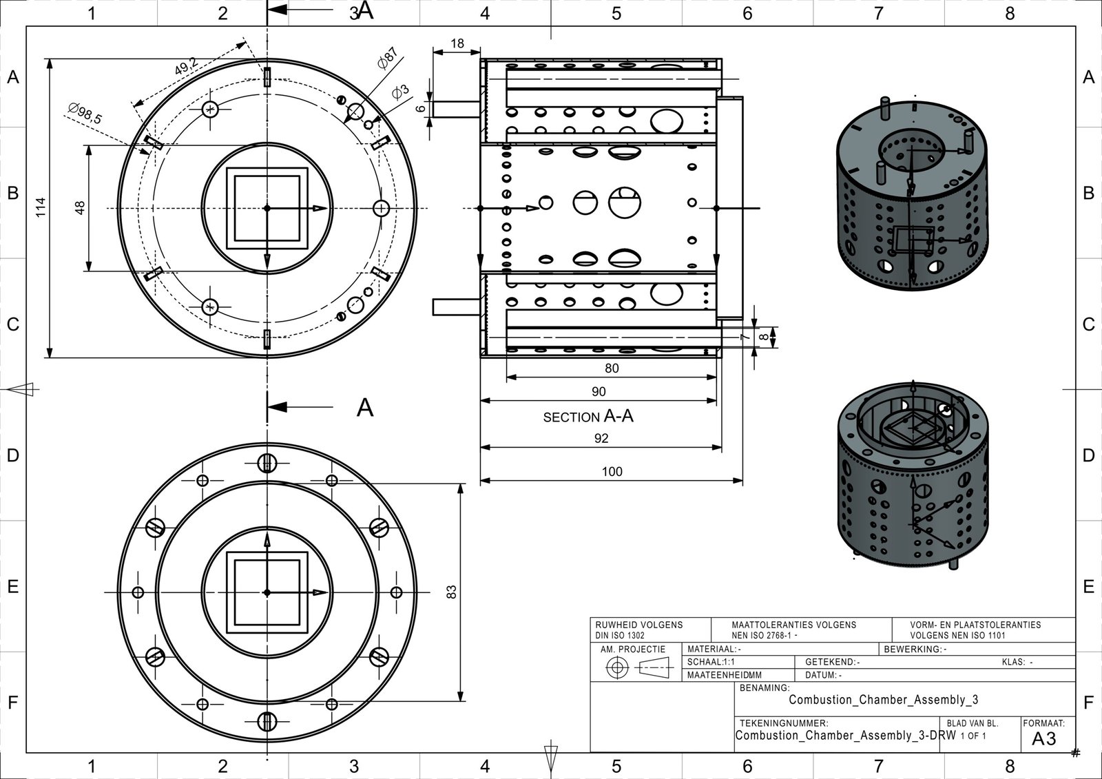
Combustion Chamber Assembly – Diffusion-based chamber designed to stabilize the flame and enable efficient fuel–air mixing. Made from multiple laser cut components.
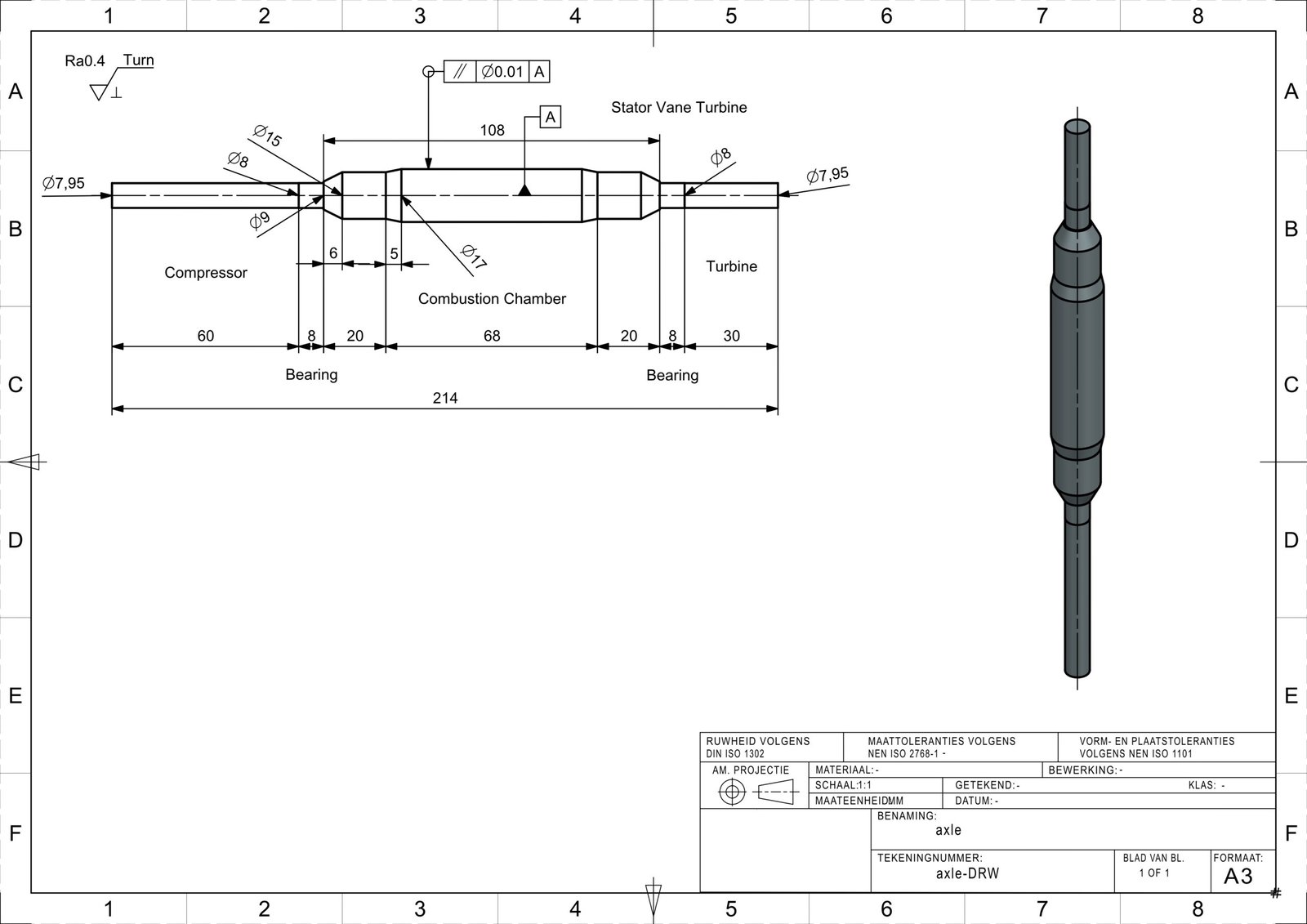
Axle – Serves as the backbone of the engine, transmitting torque between the compressor and turbine.
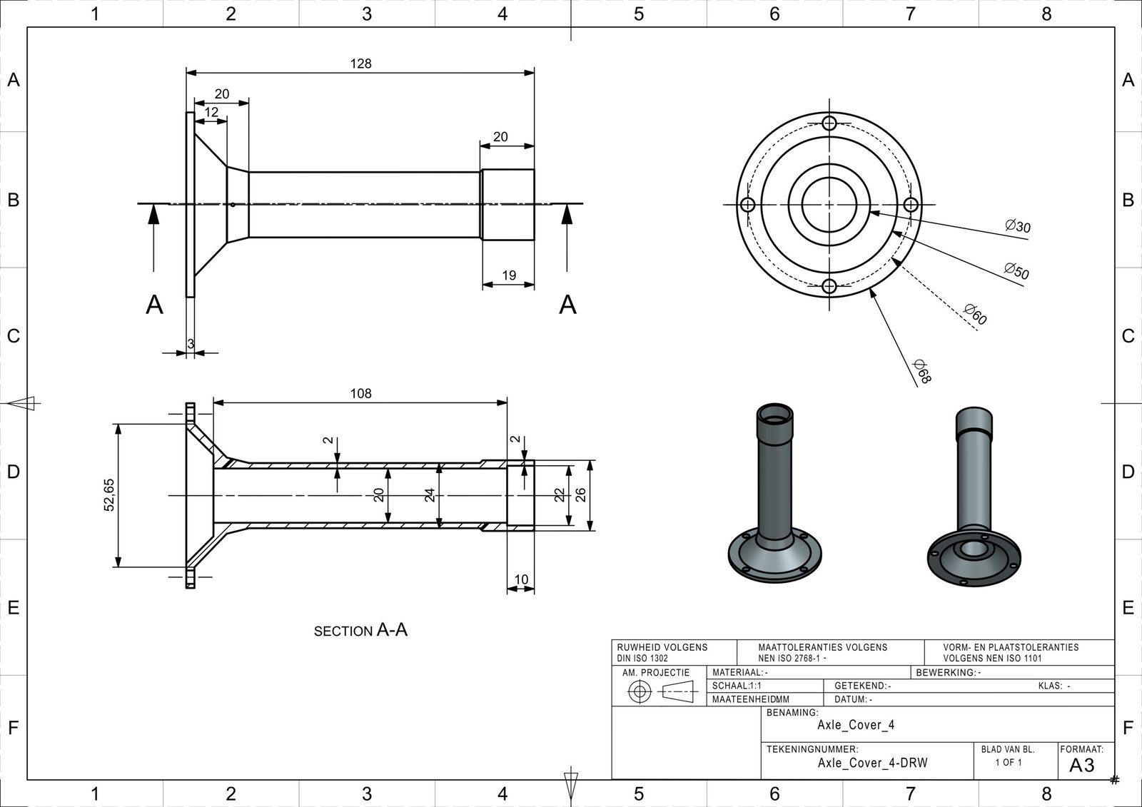
Axle Cover – Provides protection and alignment for the axle while maintaining structural integrity during operation.
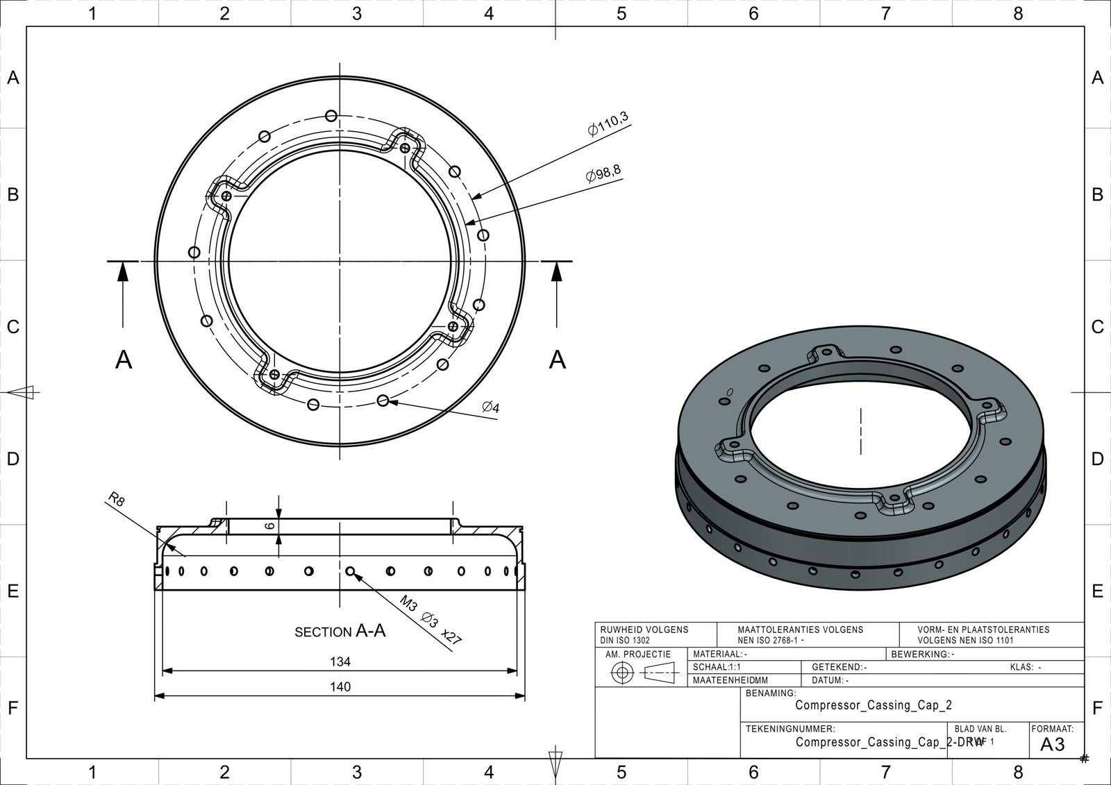
Compressor Stator Cap – Secures and seals the compressor stator, maintaining correct positioning and minimizing air leakage
3D Printed Prototyping To validate the manufacturability of the jet engine design, a complete prototype was produced using plastic 3D printing. This stage served to physically verify the sizing, fit, and tolerances of all components before committing to metal fabrication. The printed parts confirmed that the assembly aligned as intended, with each piece meeting the required dimensional accuracy. By ensuring that no adjustments were necessary, the 3D prototype provided confidence in the CAD design and reduced the risk of errors in subsequent machining processes.